Automated hydroponic control system: design, programming and implementation
How a modular controller measures pH, TDS and climate, doses nutrients with a proportional loop, waits for the tank to mix, and protects the crop with safety blocks and alerts. With worked examples, sketches and Python code.
How does a greenhouse controller keep a nutrient solution at pH 6.0 and 1000 ppm for weeks without a person standing next to the tank? It measures the solution, compares it with the grower's profile, adds a small, calculated dose of fertilizer or acid, waits for the tank to mix, and measures again. That loop, plus climate control and a set of safety blocks, is an automated hydroponic control system. The design here follows the OverGrower specification and scales from one grow box up to a 0.5 ha greenhouse.
$$ \text{Profile} \;\rightarrow\; \underbrace{\text{Sensors}}_{\text{what is it now?}} \;\rightarrow\; \underbrace{\text{Controller}}_{\text{how much to add?}} \;\rightarrow\; \underbrace{\text{Pumps}}_{\text{dose}} \;\rightarrow\; \underbrace{\text{Pause}}_{\text{let it mix}} \;\rightarrow\; \text{Sensors again} $$
An analogy. Seasoning soup: you taste it (sensor), decide it needs a little salt (controller), add a pinch (pump), stir and wait (pause), then taste again. Nobody pours in the whole salt shaker after the first taste, and neither does the controller.
1. System architecture
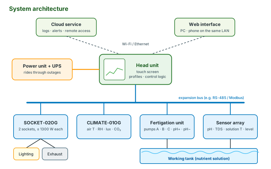
The system is modular: one head unit runs the logic and talks to expansion modules over a bus, so a small setup and a large greenhouse use the same parts in different numbers.
| Unit | Role | Key facts |
|---|---|---|
| Head unit | Touch screen, growing profiles, control logic, data logging | Hosts the web interface and the cloud connection |
| SOCKET-02OG | Switches growing devices (lights, fans, heaters) | Up to 1300 W per socket |
| CLIMATE-01OG | Measures the air | Temperature, humidity, illumination, CO₂ |
| Fertigation unit | Doses fertilizer and pH regulators | Pumps A, B, C, pH up, pH down |
| Sensor array | Measures the solution | pH, TDS/EC, solution temperature, tank level |
| Power unit | Supplies everything | UPS backup rides through short outages |
The system can be operated three ways: on the touch screen of the head unit, through a web interface from a computer or phone on the same network, and through a cloud service for logs, alerts and access from anywhere.
Operating modes
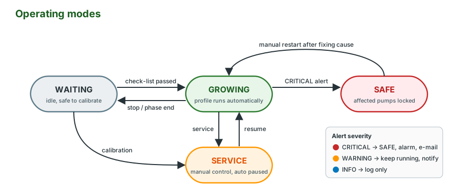
| Mode | What runs | Use it for |
|---|---|---|
| WAITING | Nothing is dosed | Setup, calibration, between crops |
| GROWING | The growing profile runs automatically | Normal operation |
| SERVICE | Manual control; automation paused | Cleaning, testing pumps, calibration |
| SAFE | Affected pumps locked after a critical error | Waiting for a person to fix the cause |
Automatic growing only starts after the pre-start check-list passes: growth phase and day, fertilizer reserves, tank configuration, water volume and mixing settings.
2. Sensors: what the system measures
| Parameter | Range | Resolution | Placement |
|---|---|---|---|
| Acidity (pH) | 3.00 – 8.00 | 0.01 | In the working tank; calibrate weekly |
| TDS salinity (ppm) | 0 – 3000 | 1 | At least 1 cm from the tank walls |
| Solution temperature (°C) | 0 – 40 | 0.1 | Immersed in the solution |
| Air temperature (°C) | 0 – 40 | 0.1 | In the growing area |
| Relative humidity (%) | 10 – 90 | 1 | In the growing area |
| Illumination (lux) | 0 – 50 000 | 1 | At canopy level |
| CO₂ (ppm) | 0 – 5000 | 1 | In the growing area |
| Tank level | Empty / Low / Medium / Full | – | Non-contact, fixed outside the tank |
pH: a voltage that follows the Nernst equation
A glass pH electrode produces a small voltage that falls by a fixed amount for each pH unit. In the ideal case the slope is
$$ S = \frac{2.303\,R\,T}{F} \approx 0.1984\,(T + 273.15)\ \text{mV per pH}, \qquad S_{25\,^\circ\text{C}} = 59.16\ \text{mV/pH} $$
and the output is about 0 mV at pH 7. Real electrodes age: the slope shrinks and the zero point drifts, which is why pH is calibrated every week and the electrode is replaced about once a year. Store it under its cap in 3 M KCl; a dry electrode responds slowly and drifts.
TDS: conductivity with temperature compensation
A TDS sensor actually measures electrical conductivity (EC), which rises about 2 % per °C. The reading is first referred to 25 °C, then converted to ppm:
$$ EC_{25} = \frac{EC_T}{1 + \alpha\,(T - 25)}, \quad \alpha \approx 0.02, \qquad \text{TDS} = f \cdot EC_{25} $$
Worked example. At 20 °C the probe reads 1.80 mS/cm. Then \(EC_{25} = 1.80 / (1 - 0.10) = 2.00\) mS/cm. On the common 500 scale \((f = 500)\) that is 1000 ppm; on the 700 scale it would be 1400 ppm. Always check which factor your meter and your fertilizer chart use.
Two-point calibration
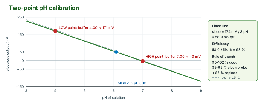
Both pH and TDS are calibrated by measuring two known solutions and fitting a straight line through them:
$$ \text{pH}(E) = \text{pH}_H + (E - E_H)\,\frac{\text{pH}_L - \text{pH}_H}{E_L - E_H} $$
Worked example. The probe reads 171 mV in pH 4.00 buffer and −3 mV in pH 7.00 buffer.
| Quantity | Calculation | Value |
|---|---|---|
| Slope | \((171 - (-3)) / (7 - 4)\) | 58.0 mV/pH |
| Efficiency | \(58.0 / 59.16\) | 98 % (good) |
| Unknown sample at 50 mV | \(7 + (50 + 3) \cdot \tfrac{4 - 7}{171 + 3}\) | pH 6.09 |
A third buffer (pH 6.0) checks the result: if it reads more than about 0.05 off, repeat the calibration.
| Step | pH sensor (weekly) | TDS sensor (monthly) |
|---|---|---|
| Mode | WAITING or SERVICE | WAITING or SERVICE |
| Clean | Rinse in distilled water, soak 15 min in 3 M KCl, rinse | Rinse in deionised water, wipe with 70 % isopropyl alcohol, dry |
| LOW point | pH 4.00 buffer, wait 30–60 s, fix | 500 ppm solution, wait 30 s, fix |
| HIGH point | pH 7.00 buffer, wait, fix | 2000 ppm solution, wait, fix |
| Store | Coefficients to non-volatile memory | Coefficients to non-volatile memory |
| Verify | pH 6.0 buffer | 1000 ppm solution (optional) |
3. Regulation: dosing pH and TDS
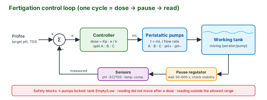
Fertigation has two loops. TDS is raised by proportional pumping of a multi-component fertilizer (pumps A, B and C in a fixed ratio). pH is moved by acid or alkali dosing. Both run in the same rhythm: dose, pause, read.
Proportional dosing
Let \(e = \text{TDS}_\text{target} - \text{TDS}_\text{measured}\) and let \(k\) be how many ppm one millilitre of fertilizer mix adds to this tank (measure it once: dose 20 mL into 100 L, see +40 ppm, so \(k = 2\) ppm/mL; \(k\) scales with \(1/V\)). The controller doses
$$ v = K_p\,\frac{e}{k}\ \text{mL}, \qquad t_\text{pump} = \frac{v_\text{component}}{q_\text{pump}} $$
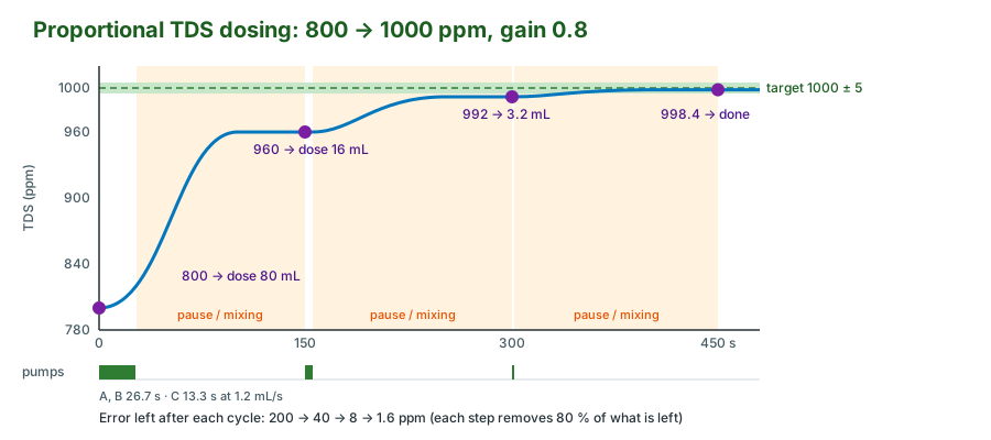
with a gain \(K_p < 1\). Each cycle removes the fraction \(K_p\) of the remaining error, so after \(n\) cycles
$$ e_n = e_0\,(1 - K_p)^n, \qquad n \ge \frac{\ln(\text{tol}/e_0)}{\ln(1 - K_p)} $$
Why not \(K_p = 1\)? Because fertilizer can only be added, never taken out. If \(k\) is a little wrong, a full-size dose overshoots and the only fix is diluting the whole tank. A gain of about 0.8 approaches the target from below.
Worked example. 100 L tank at 800 ppm, target 1000 ± 5 ppm, \(k = 2\) ppm/mL, ratio A : B : C = 2 : 2 : 1, every pump calibrated to 1.2 mL/s.
| Cycle | Reading | Error | Dose \(0.8\,e/k\) | Pump times A / B / C |
|---|---|---|---|---|
| 1 | 800.0 | 200 | 80.0 mL | 26.7 / 26.7 / 13.3 s |
| 2 | 960.0 | 40 | 16.0 mL | 5.3 / 5.3 / 2.7 s |
| 3 | 992.0 | 8 | 3.2 mL | 1.1 / 1.1 / 0.5 s |
| 4 | 998.4 | 1.6 | – | within tolerance, stop |
The formula agrees: \(n \ge \ln(5/200)/\ln(0.2) = 2.3\), so three doses.
pH regulation
pH works the same way with two pumps: below target → alkali, above target → acid. The response is not linear, because nutrient solutions are buffered: the first millilitres of acid move pH little, later ones much more. Keep doses small (the controller can learn "pH per mL" from previous cycles) and always regulate pH after TDS, since fertilizer itself shifts pH.
Pause and stability
After a dose the solution needs time to mix. The pause regulator (30–600 s, user configurable) blocks new readings until then, and the reading is only trusted once it is stable: the standard deviation of the last few samples is below a threshold.
$$ \sigma = \sqrt{\frac{1}{N}\sum_{i=1}^{N} (x_i - \bar{x})^2} < \sigma_\text{max} $$
Worked example. Six pH samples, 10 s apart: 6.02, 5.98, 6.01, 6.00, 5.99, 6.00. Mean 6.000, squared deviations sum to 0.0010, so \(\sigma = \sqrt{0.0010/6} = 0.013\). That is below 0.05: stable, dosing may continue. Typical thresholds are 0.05 pH or 10 ppm over 60 s. Mixing itself is a duty cycle on the aerator or circulation pump, for example 15 min on, 5 min off.
Controller error
If the controller doses but the reading does not move beyond a timeout, something outside the software is wrong. The system raises a pH or TDS controller error, locks the pumps and waits for a manual restart. Typical causes:
| Cause | Check |
|---|---|
| Empty fertilizer or regulator reservoir | Refill, re-prime the tubing |
| Kinked or air-locked tubing | Straighten, re-prime with a syringe |
| Dead zones, too little mixing | Increase the mixing duty cycle |
| Sensor too close to the dosing point | Move it away from the inlet |
| Air bubbles or biofilm on the probe | Clean and tap the probe |
| Temperature stratification | Mix, check the solution heater |
Pump calibration
Dosing is only as good as the flow rate \(q\). Run each pump (pH up, pH down, A, B, C) into a graduated cylinder for a fixed time, three times.
Worked example. 30 s runs give 36.2, 35.8 and 36.5 mL. Mean 36.17 mL, so \(q = 1.206\) mL/s; the largest deviation is 0.9 %, well inside ±5 %. A 10 mL dose then takes \(10 / 1.206 = 8.3\) s. Recalibrate after replacing tubing; if runs disagree by more than 5 %, look for air leaks, kinks or worn peristaltic rollers.
4. Tanks, irrigation and climate
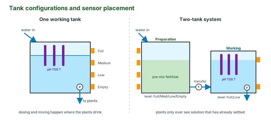
| Aspect | One working tank | Two-tank system |
|---|---|---|
| Sensors | All sensors in the working tank | pH/TDS/temperature in the working tank, level in both |
| Level states | Full, Medium, Low, Empty | Working: Full/Low; preparation: Full/Medium/Low/Empty |
| Water supply | Fill the working tank when Low | Fill the preparation tank, transfer when needed |
| Solution preparation | Mix directly in the working tank | Pre-mix, transfer once stable (solution transfer function) |
| Trade-off | Simpler, fewer pumps | More hardware, no concentration swings at the roots |
Irrigation modes
| Mode | Behaviour | Typical use |
|---|---|---|
| Constant | Solution flows non-stop | NFT, deep water culture |
| Periodic | On/off schedule, e.g. 15 min on / 45 min off | Ebb and flow, drip, aeroponics |
| Blocking | Stops the pump on tank Empty/Low or when pH/TDS leave the allowed range | Protects pump and roots |
Climate: light, humidity, power
The daily regime sets the photoperiod, e.g. 18/6 (18 h light, 6 h dark). A lux sensor does not measure photosynthetic light directly, but for a rough daily light integral (DLI) a conversion factor works:
$$ \text{DLI} = \text{PPFD} \cdot \frac{3600 \cdot h}{10^6}\ \ \text{mol·m}^{-2}\text{·d}^{-1}, \qquad \text{PPFD} \approx c \cdot \text{lux} $$
Example: 20 000 lux of sunlight-like light with \(c \approx 0.0185\) gives about 370 µmol·m⁻²·s⁻¹; over 18 h that is \(370 \cdot 64\,800 / 10^6 \approx 24\) mol·m⁻²·d⁻¹. The factor \(c\) depends on the light source, so calibrate it against a PAR meter for LEDs.
Humidity is easier to control as vapour pressure deficit (VPD), which is what drives transpiration:
$$ e_s(T) = 0.6108\,\exp\!\Big(\frac{17.27\,T}{T + 237.3}\Big)\ \text{kPa}, \qquad \text{VPD} = e_s(T)\,\Big(1 - \frac{RH}{100}\Big) $$
Example: 25 °C and 60 % RH: \(e_s = 3.17\) kPa, so VPD = 1.27 kPa, a comfortable value for most crops in vegetative growth.
Socket power. Each SOCKET-02OG socket carries at most 1300 W (≈ 5.7 A at 230 V). Two 600 W LED fixtures (1200 W) fit; three (1800 W) do not, so the socket drives the coil of an external contactor that switches the lights. Leave margin for LED and motor inrush.
Adding a module
- Connect the module to the head unit's expansion port.
- In Device Manager, add the new SOCKET-02OG.
- Assign it to a climate zone.
- Assign socket 1 → Lighting, socket 2 → Exhaust.
- Check every load is ≤ 1300 W; otherwise add a contactor.
- Test each function from the interface before starting growth.
Safety and alerts
| Category | Examples | Severity | Action |
|---|---|---|---|
| Controller errors | pH, TDS or CO₂ controller error | CRITICAL | Pumps locked, SAFE mode, manual restart |
| Tank status | Working tank empty, level sensor error | CRITICAL | Irrigation blocked, refill now |
| Sensor maintenance | Cleaning due, calibration drift | WARNING | Schedule maintenance |
| Fertilizer levels | Component A low, pH regulator empty | WARNING | Refill, dosing may fail |
| System status | Power on UPS, network lost, phase complete | INFO | Log only |
Critical errors show a red icon, sound the (configurable) alarm and send an e-mail with timestamp, device ID, description, current readings and recommended action. E-mail needs an internet connection and SMTP settings (host, port 465 for SSL or 587 for STARTTLS, credentials, sender and recipients); send a test message and whitelist the sender before relying on it.
5. Code: sensor calibration and temperature compensation
from dataclasses import dataclass

@dataclass
class TwoPointCal:
    """Straight line through two reference points: raw -> value."""
    raw_low: float
    ref_low: float
    raw_high: float
    ref_high: float

    @property
    def slope(self):
        return (self.ref_high - self.ref_low) / (self.raw_high - self.raw_low)

    def __call__(self, raw):
        return self.ref_low + (raw - self.raw_low) * self.slope


def ph_efficiency(cal, temp_c=25.0):
    """Electrode slope as a fraction of the ideal Nernst slope."""
    ideal = 0.1984 * (temp_c + 273.15)          # mV per pH
    return abs(1 / cal.slope) / ideal


def tds_ppm(ec_ms_cm, temp_c, alpha=0.02, factor=500):
    """Refer EC to 25 °C, then convert to ppm (500 or 700 scale)."""
    ec25 = ec_ms_cm / (1 + alpha * (temp_c - 25))
    return factor * ec25


ph = TwoPointCal(raw_low=171, ref_low=4.00, raw_high=-3, ref_high=7.00)
print(f"pH at 50 mV: {ph(50):.2f}, efficiency {ph_efficiency(ph):.0%}")  # 6.09, 98%
print(f"TDS: {tds_ppm(1.80, 20):.0f} ppm")                               # 1000 ppm
6. Code: proportional dosing with a controller-error check
from dataclasses import dataclass, field

@dataclass
class TDSController:
    target: float
    tolerance: float = 5.0
    gain: float = 0.8
    ppm_per_ml: float = 2.0                     # k, measured for this tank
    ratio: dict = field(default_factory=lambda: {"A": 2, "B": 2, "C": 1})
    min_change: float = 3.0                     # a dose must move the reading this much
    max_dry_doses: int = 3
    dry_doses: int = 0
    blocked: bool = False

    def step(self, reading, last_reading=None, last_dose_ml=0.0):
        """Return {component: mL} to dose now; empty dict means do nothing."""
        if self.blocked:
            return {}
        if last_dose_ml > 0 and last_reading is not None:
            if abs(reading - last_reading) < self.min_change:
                self.dry_doses += 1
                if self.dry_doses >= self.max_dry_doses:
                    self.blocked = True         # controller error: manual restart
                    return {}
            else:
                self.dry_doses = 0
        error = self.target - reading
        if error <= self.tolerance:             # fertilizer can only raise TDS
            return {}
        total = self.gain * error / self.ppm_per_ml
        parts = sum(self.ratio.values())
        return {k: total * v / parts for k, v in self.ratio.items()}


# Simulated 100 L tank, pumps at 1.2 mL/s
tds, ctl, flow = 800.0, TDSController(target=1000), 1.2
last, dosed = None, 0.0
while dose := ctl.step(tds, last, dosed):
    dosed = sum(dose.values())
    print(f"TDS {tds:6.1f} -> {dosed:5.1f} mL, A {dose['A'] / flow:4.1f} s")
    last, tds = tds, tds + dosed * ctl.ppm_per_ml   # on hardware: run pumps, then pause
print(f"TDS {tds:6.1f} -> done")
The full simulation, with a tank model, is in dosing_sim.py.
To simulate an empty reservoir, replace dosed * ctl.ppm_per_ml with 0 in the last line of the loop: after three doses that change nothing the loop stops with ctl.blocked == True, the controller error.
7. Code: stability check and e-mail alerts
import smtplib
import statistics
from email.message import EmailMessage

def is_stable(samples, max_std):
    """True when the last samples vary less than max_std (population std dev)."""
    return len(samples) >= 3 and statistics.pstdev(samples) < max_std

print(is_stable([6.02, 5.98, 6.01, 6.00, 5.99, 6.00], 0.05))   # True (σ = 0.013)

def send_alert(cfg, severity, text, readings):
    msg = EmailMessage()
    msg["Subject"] = f"[{severity}] {cfg['device_id']}: {text}"
    msg["From"], msg["To"] = cfg["sender"], ", ".join(cfg["recipients"])
    body = [text, ""] + [f"{k}: {v}" for k, v in readings.items()]
    msg.set_content("\n".join(body))
    with smtplib.SMTP(cfg["host"], 587, timeout=10) as s:   # 587 = STARTTLS
        s.starttls()
        s.login(cfg["user"], cfg["password"])
        s.send_message(msg)

# send_alert(cfg, "CRITICAL", "TDS controller error: pumps locked",
#            {"TDS": "812 ppm", "pH": 6.1, "Tank": "Low"})
Common problems and fixes
| Problem | Fix |
|---|---|
| pH drifts between calibrations | Clean the probe, store it wet in 3 M KCl, check efficiency; replace below ~85 % |
| TDS overshoots the target | Lower the gain, re-measure \(k\), lengthen the pause |
| Readings jump after every dose | Move sensors away from the dosing inlet, increase mixing |
| Controller error with full reservoirs | Re-prime tubing, check for kinks and worn pump rollers |
| Wrong ppm compared with another meter | Check the conversion factor (500 vs 700) and temperature compensation |
| Lights trip the socket | Load above 1300 W or high inrush: use a contactor |
| No alert e-mails | Test SMTP settings, whitelist the sender, check the internet connection |
Glossary
| Term | Meaning |
|---|---|
| Access point mode | The controller creates its own Wi-Fi network for direct connection |
| Check-list | Pre-start verification of all critical settings |
| Climate zone | An area with its own growing profile and assigned devices |
| Cyclical injection | Scheduled dosing of biostimulants or additives at set volumes and intervals |
| Daily regime | Photoperiod in the profile, e.g. 18/6 |
| Device Manager | Menu for adding, removing and configuring modules |
| Fertigation unit | Subsystem that mixes fertilizer and regulates pH |
| Growing controls | Main menu for solution and climate zones and the growing process |
| Growing profile | Block program of phase-specific targets (pH, TDS, fertilizers, daily regime) |
| Service mode | Manual override that pauses automation |
| Smooth change | Gradual transition of targets between growth phases to reduce plant stress |
| Solution zone | Settings for the solution, tank system and fertigation |
Quick review
- What scale does the system cover? From a single setup up to a 0.5 ha greenhouse.
- What must a growing profile define? Solution zone: pH, TDS and fertilizers. Climate zone: the daily regime.
- When is solution transfer available? Only in the two-tank configuration.
- What triggers a controller error? Dosing happened but the reading did not change within the timeout; pumps stay locked until a manual restart.
- How is the pH electrode stored? Under its cap in 3 M KCl, never dry; replace it about yearly.
- What are the three ways to operate the system? Touch screen, local web interface, cloud service.
Further reading
- Howard M. Resh, Hydroponic Food Production, CRC Press: nutrient solutions, systems and crops
- Python
smtplibdocumentation, for the alert code in section 7 - pymodbus documentation, for talking to RS-485 / Modbus sensor modules
Try it yourself
- Calibrate a pH probe with two buffers, compute its slope and efficiency, and check it with a third buffer.
- Run the simulation in section 6 with gains 0.5, 0.8 and 1.2. How many cycles does each need, and which ones overshoot when the \(k\) you entered is 20 % smaller than the real one?
- Log pH every 10 s after a dose and find the shortest pause after which
is_stablereturnsTrue. - Compute VPD for your grow room at day and night temperatures and decide which humidity targets keep it between 0.8 and 1.2 kPa.